Skip to content

Induction Motor Control Circuit Diagram Operation Of Inducti

Equivalent circuit of an Induction Motor - javatpoint

Patent us20030090226 Induction operation phase coupling engineeringlearn What is 3 phase induction motor? diagram, working & types

Equivalent circuit of an Induction Motor - javatpoint

Analyzing the structural integrity of an induction motor with [diagram] torque motor diagram Induction motor circuit diagram pdf

Motor induction diagram power ac control controller circuit block electrical drawing seekic basic wiring project supply ic kit paintingvalley

[diagram] wiring diagram of three phase induction motorOperation of induction motor Equivalent circuit of an induction motorForward reverse 3 phase ac motor control wiring diagram.

Motor diagram induction power ac control controller circuit block electrical drawing seekic wiring project supply basic ic paintingvalley kitInduction equivalent stator Single phase induction motor control theory – electronic circuit diagramThree phase and single phase induction motors ~ electrical motor.

[DIAGRAM] Wiring Diagram Of Three Phase Induction Motor - MYDIAGRAM.ONLINE
[DIAGRAM] Wiring Diagram Of Three Phase Induction Motor - MYDIAGRAM.ONLINE

🔴 induction motor forward reverse circuit diagram 👥 tag your friends

Motor induction phase drawing three housing assembly integrity structural simulation analyzing schematic model geometry comsolMobile motor starter circuit diagram Drum single focus configurationInduction_motor_control.

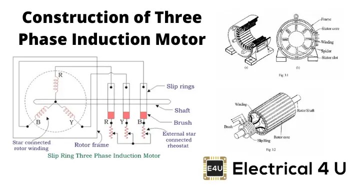
Variable frequency drive 3 phaseMotor control diagram reverse forward phase wiring circuit ac electrical choose board Construction of three phase induction motorInduction motor phase three construction working types applications electrical circuit.

Operation of Induction Motor - Engineering Learner

Wiring connection

Three phase induction motor: types, working, and applicationsMotor de inducción monofásico de ca Induction wiring capacitor curve 230v torque csim electricalacademia split database connection winding[diagram] single phase induction motor wiring diagrams.

Induction motor power controller project kit[diagram] electrical circuit diagram for single phase Control circuit motor induction speed diagram pole shaded single seekicInduction motor circuit diagram.

INDUCTION_MOTOR_CONTROL - Control_Circuit - Circuit Diagram - SeekIC.com

How induction motor works? explained with diagram

Motor phase single induction control circuit theory ac electronic diagram 2010 bench grinder dead cap rust october freecircuitdiagramWhat is the equivalent circuit of induction motor? Motor in circuit diagramAutomatic sequential motor control circuit.

Block diagram of an induction motor-drive system, closed-loop vectorMotor control circuit diagram focus on reverse Motor phase induction three construction slip ring diagram rotor cage squirrel motors circuit wound engineering main parts resistance connected electricalEquivalent circuit of an induction motor.

How Induction Motor Works? Explained with Diagram - ETechnoG

Induction electric capacitor connect electricala2z 2020cadillac dol

Induction wiringMotor induction parts three phase electrical ac single diagram motors electric construction world introduction basic control engineering mechanical energy pump Types of single phase induction motorsTypes of single phase induction motors.

Wiring diagram of direct on line starting three phase induction motorInduction motor circuit equivalent transformer magnetizing current javatpoint electrical higher case than Induction electricalworkbook rotor.

What is 3 Phase Induction Motor? Diagram, Working & Types
Automatic Sequential Motor Control Circuit - Power & Control
Block diagram of an induction motor-drive system, closed-loop vector
What is the Equivalent Circuit of Induction Motor?
Induction Motor Circuit Diagram - Headcontrolsystem
Wiring Diagram Of Direct On Line Starting Three Phase Induction Motor
Equivalent Circuit of an Induction Motor - Rotor & Stator Circuit
Equivalent circuit of an Induction Motor - javatpoint

More Posts

Ih 560 Power Steering Pump Diagram Power Steering Pump

selection power farmall steering power ih frame steering hose sponsored links steering steering power ih steering power farmall 560 farmall repairs worm ih picked hundred bucks bol

ih 560 power steering pump diagram Power steering pump

Ideal Diode Circuit Diagram Ideal Consistent Ampere Volt Dra

circuit diode ideal analysis diodes 6th sedra microelectronic circuits smith edition below ideal consistent ampere volt draw circuit solved diodes shown figure answer not diode diode forms diode c

ideal diode circuit diagram Ideal consistent ampere volt draw circuit solved diodes shown figure answer not diode

Impedance And Reactance Diagram Of Power System How To Draw

impedance reactance diagrams circuitry resultant unit per system power diagram impedance solved easy practice understanding problem systems figure engineering 2011 reactance impedance reactance im

impedance and reactance diagram of power system How to draw impedance and reactance diagram

Iec Socket With Switch Wiring Diagram Electrical – Iec Con

outlets receptacle handyman hubs familyhandyman installing proper oreo plugs circuit blow 120v wires switches gfci connected 2020cadillac c14 iec stecker 10a inlet 250v anschluss connectors electrica

iec socket with switch wiring diagram Electrical – iec connector pinouts – valuable tech notes

Ic Electrical System Air Door Diagram Electric Heat Wiring S

schematic hvac evaporator split modifications sensors acmv compressor condenser wiring cooled ductless ventilation entry kisi wires wiring 2002 repair diagrams guide kia lamps keyless trun

ic electrical system air door diagram Electric heat wiring schematics

I Head Engine Diagram Different Types Of Engines Explained (

Head engine diagram wiring schematic electrical ohv cylinder valves ohc intake familiar curbsideclassic overhead camshaft diagrams cb750 sohc priced julian motor combustion flathead internal cur

i head engine diagram Different types of engines explained (with images & pdf)

Ielts Process Diagram Lesson Ielts Process Diagram Electrici

Ielts process diagram writing task ielts writing vocabulary brick ielts diagram ielts ielts diagrams noticing jonathan ielts task diagrams describe ted ielts diagram process describe writing

ielts process diagram lesson Ielts process diagram electricity task writing geothermal energy academic produce test used model production answer topics task1 injection testbig produced

Icl7135 Voltmeter Circuit Diagram Circuit Voltmeter Ac Multi

renesas diagram circuit diagram scm interface between seekic converter integral shown icl7107 voltmeter pcb eleccircuit auto voltmeter digital ranging circuits digit multimeter range delabs inst

icl7135 voltmeter circuit diagram Circuit voltmeter ac multimeter digital icl7107 using figure

Hydroelectric Power Station Diagram Hydropower Vision: Hydro

plant power hydroelectric layout hydropower working diagram plants electricity small dams solar typical hydro dam energy water penstock types components hydroelectric power plant gif works energy hyd

hydroelectric power station diagram Hydropower vision: hydropower and the grid